This project was carried out with the invaluable collaboration of
 and
and 
please see a full listing of all contributors at the bottom of this post
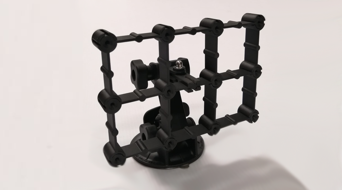
the final modular Aero Rake concept
Project Outline
In early June 2021, Arno Seyfert from Custom Works proposed a collaborative project with one of his clients, Scuderia Scribante, a locally based racing team who raced two Lamborghini Huracans in the newly established national South African GT Racing series. Of course, we immediately wet ourselves and, in fairly quick time, we had arranged a meeting with the team at their very impressive base, and were staring open-mouthed at some extremely exotic machinery.
We were warmly welcomed by Team Manager, Byron Teengs and his staff, and the start of an exciting aero profiling project was put into play.
The initial idea of the project is to establish a capability to profile the aerodynamics of the car using CFD techniques and then to quantify those results with what the race drivers encounter on track days, with the ultimate objective of being able to advise aero tweaks and configuration changes to improve performance.
This would also enable our team to seriously enhance its CFD knowledge-base and capability which would then inform other projects as well as spill back into the engineering curriculum.
There are no illusions that this is a huge challenge, and one which we anticipate will progress inch-by-inch over several years, as CFD and on-track calibration is a daunting task that is very much the preserve of Formula 1 teams and their ilk...as such, a very much crawl-stand-walk-run approach would be needed, as CFD is not an engineering anaysis sector that is straight-forward and certainly not for occasional dabbling.
In order to achieve this, a multi-year plan of action was set-up with many short-term initial learning milestones established, on what we anticipate will be a long but rewarding journey and engineering challenge.
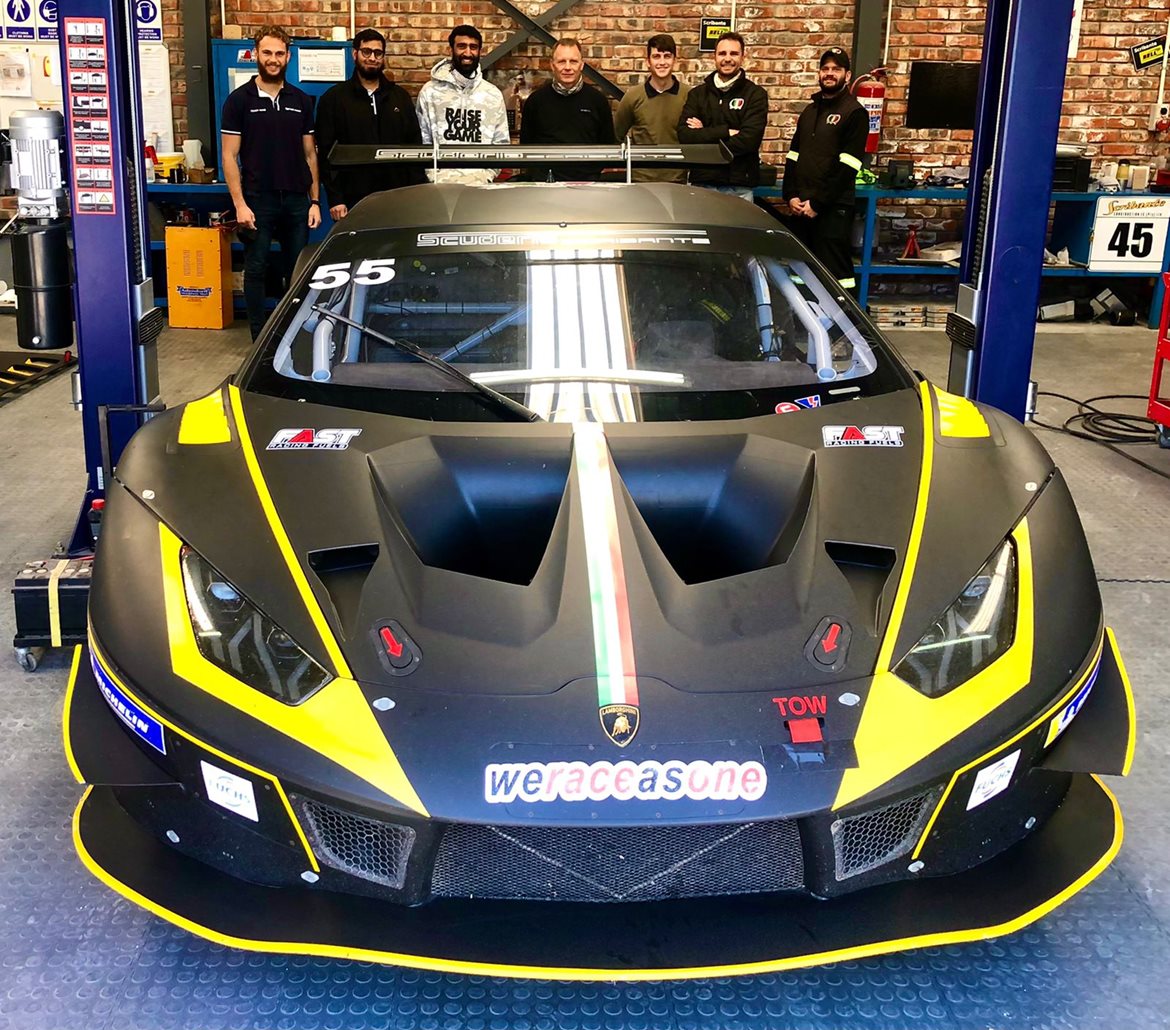
Scuderia Scribante's awesome GT3 Lamborghini Huracan EVO racing car together with the AEDG Team
Overview
The first year's objective of this project was to establish a step-wise learning approach to CFD simulations and physical flow testing that allows the engineer to apply these methods to any external aerodynamic component design, and to run simulations that have credibility in comparison to real-world outputs.
This was planned as an incremental process, starting with exposure to fundamental fluid dynamic theory, then benchmark CFD simulation of simple shapes, supplemented by basic air speed testing, and then pressure testing of an air foil in a wind tunnel using sophisticated data capture equipment. This would then inform the design of a modular aero-rake that would be reconfigurable to take on most shape configurations.
This project was to serve as an initial stepping stone on a longer journey for the follow-up project involving the external aerodynamic mapping and profiling of a GT3 Lamborghini Huracan EVO racing car…
Initial Benchmark Simulations
A repository of Fluid Dynamics fundamentals and CFD tutorials were set up as a quick reference learning platform for the AEDG Team members on a Moodlec platform, onsisting of a wealth of information from basic to advanced level including case studies across numerous applied sectors. This was to be a self-learning platform for the team members to work through on their own time.
Benchmark simulations on basic geometric shapes were then planned using SolidWorks Flow, as this was a relatively solid yet user-friendly option to carry out simple CFD studies, within a fairly familiar environment.
SolidWorks Flow is an adaption of the FlowEFD solver and has a fairly good reputation as a CFD solver as long as the simulations are relatively simplistic otherwise the overhead can seriously impact a computer. We started off analysing a simple solid sphere.
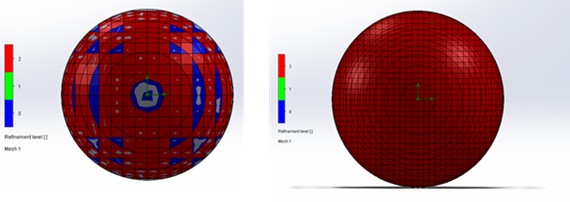
mesh refinement of the solid sphere
The image on the left shows the initial mesh automatically generated by the software, while the image on the right shows a manually improved mesh using a curvature refinement. The results achieved were comparable to reputable benchmark results found online, and so we were off to a good start.
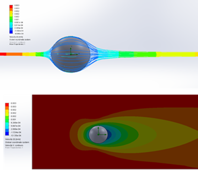
mesh refinement of the solid sphere
After the sphere a flat plate was analysed. This illustrated how the Reynolds number and boundary layer develops over the length of the plate.
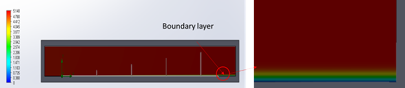
flat plate analysis showing detail of the boundary layer
The complexity was then stepped up again and so the flow over a simplified automotive body called an Ahmed body was simulated.
The flow was simulated at varying rear slope angles to investigate the effect this angle would have on the aerodynamic forces (lift and drag) generated by the vehicle.
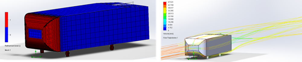
an Ahmed Body representing a simplified vehicle
After several other benchmark simulations, a significant step-up was made, to an online model of a Williams Racing F1 Wing - this was analysed to investigate the effect the rear winglet angle has on the aerodynamic forces induced by the wing.
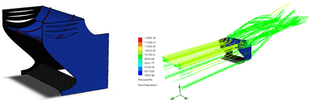
flow on an F1 Williams rear wing assembly
ASB Air Speed Sensor Quantification
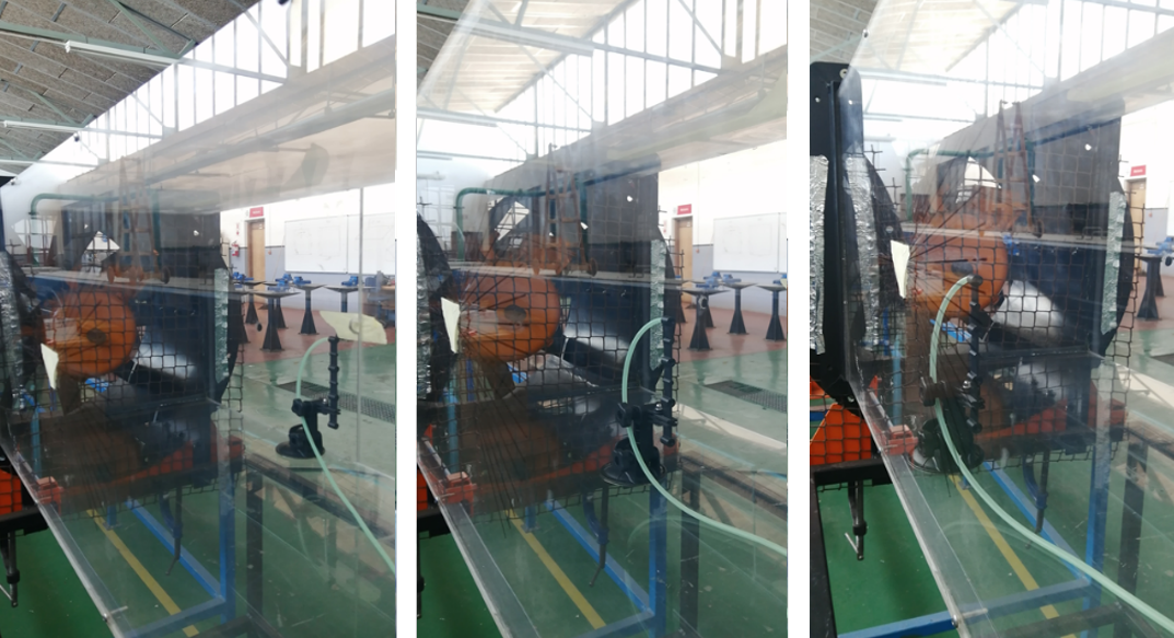
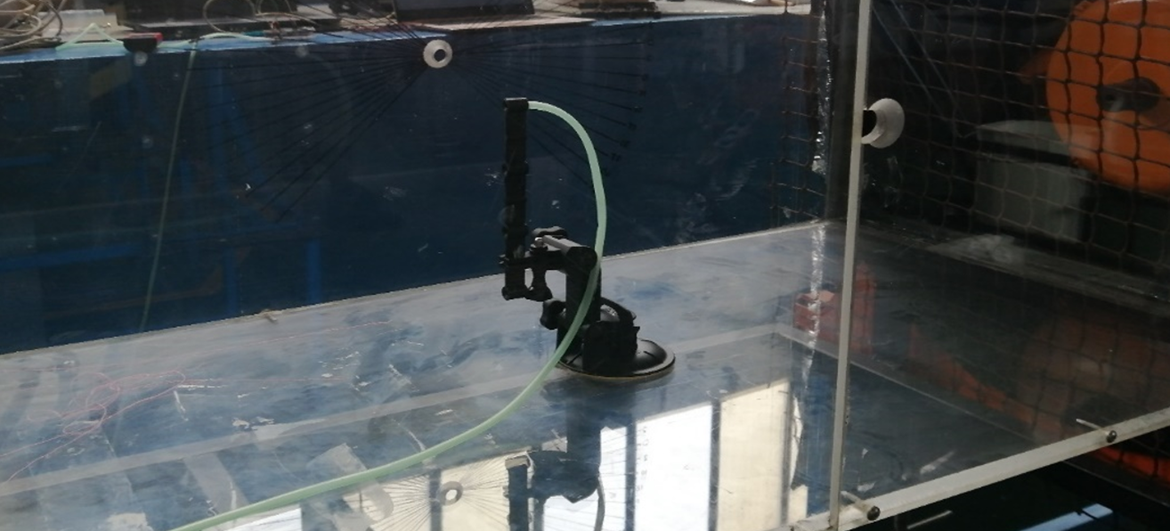
A simple experiment was carried out to verify air speed in preparation for the Aero rake design to help get the heads around air speed measurement using an ASB Air Speed sensor.
The airspeed sensor had to be calibrated to a known pressure value before the airspeeds could be measured as the airspeed sensor has a HEX output due to the I2C communication used by the Arduino. This was done by connecting the airspeed sensor to a 3D printed connector that split the air tubing into two. The one end was connected to the aero rake, and the other end to a digital manometer.
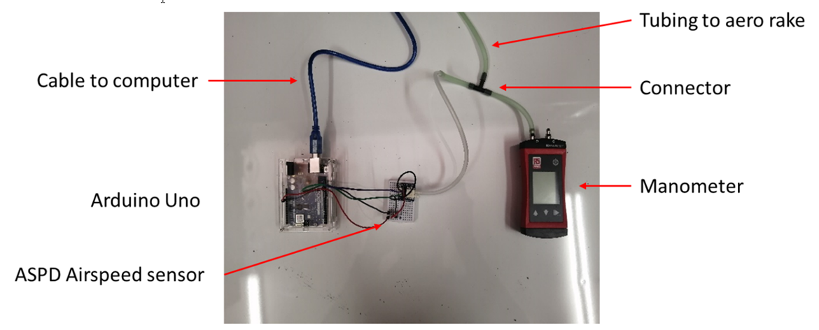
the air speed sensor experiment set-up
The aero rake was assembled and placed in the wind tunnel at 3 different positions. The tubing was then connected to the back of the aero rake. The angle of the aero rake was adjusted using a spirit level to ensure that it was aligned with the airflow.
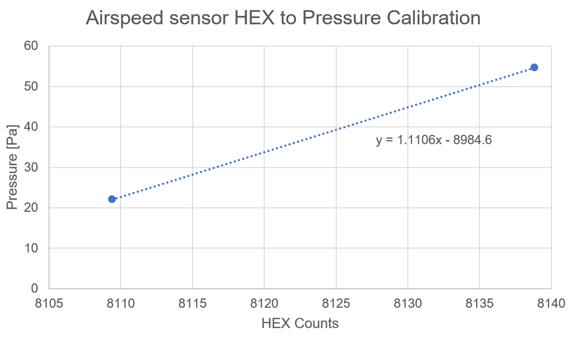
There were many datapoints and so the averages of the airspeed sensor readings with the fan off, and the fan on was taken and compared with the manometer readings to establish a transfer function from HEX counts to pressure.
The transfer function was then put to the test by converting the test data points measured for the calibration run to pressures and comparing them to the manometer readings. From the data it seems that the sensor favours better accuracy at higher speeds than lower speeds, as point 2 was in the middle of the wind tunnel where the speed was the lowest due to the fan hub creating a “hole” in the fan suction force. The most accurate result was on the left side of the wind tunnel at point 1, where the airspeed, and thus differential pressure, was the highest.
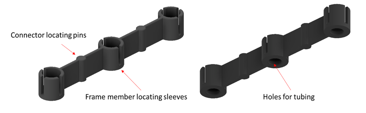
Aero Rake Design
While the benchmark tests were being completed, a modular 3D printed aero rake was designed to be used with differential pressure sensors in the physical testing of a NACA23012 air foil in an in-house small scale wind tunnel apparatus.
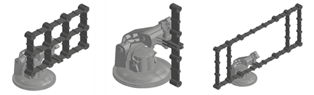
The design consists of modular 3D printed components. The number of input channels on each component can be changed by changing the number of repeated instances in the rectangular pattern within the CAD environment. This allows multiple aero rake configurations to be manufactured in a short period of time.
The setup is easily reconfigured by sliding the frame members out of the sleeves and repositioning them in the desired locations.
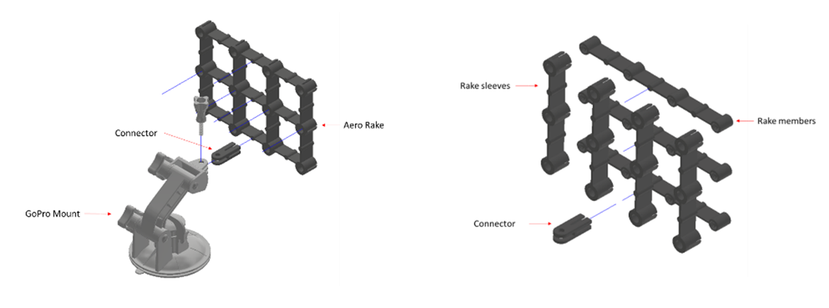
The sleeves have locating pins where the connector can be slotted on to, which connects the aero rake onto an available GoPro mount.
The sleeve houses the aero rake member and keeps it aligned with the oncoming air stream.
Each sleeve has a 3-way slot so that the members can be connected in any direction. The back of the sleeves is open to allow tubing to be connected through it onto the outlets of the members
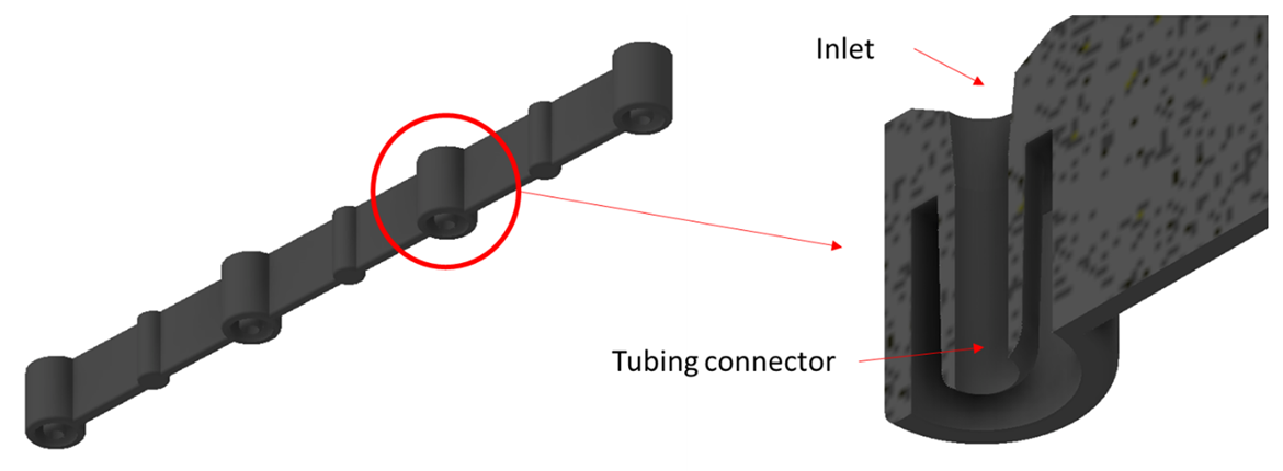
The aero rake member has a tapered back outlet port to allow easy connection of the silicone air tubing that connects the aero rake to the differential pressure sensors.
The front inlet of the members is where the air enters the aero rake.
The front is countersunk to assist in directing the airflow into the tubing and prevent excessive vortex generation by abruptly flat surfaces.
The members also have locating pins which can be used to connect the aero rake to the connector
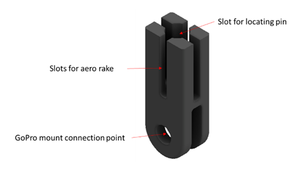
The aero rake connector is used to connect the aero rake to the GoPro mount.
It has a 4-way connection slot so that the aero rake can be orientated in different directions.
The central locating hole is used to locate the connector on the aero sleeve or member locating pins. The connector connects to the GoPro mount by means of a 5 mm bolt.
CFD Benchmarking
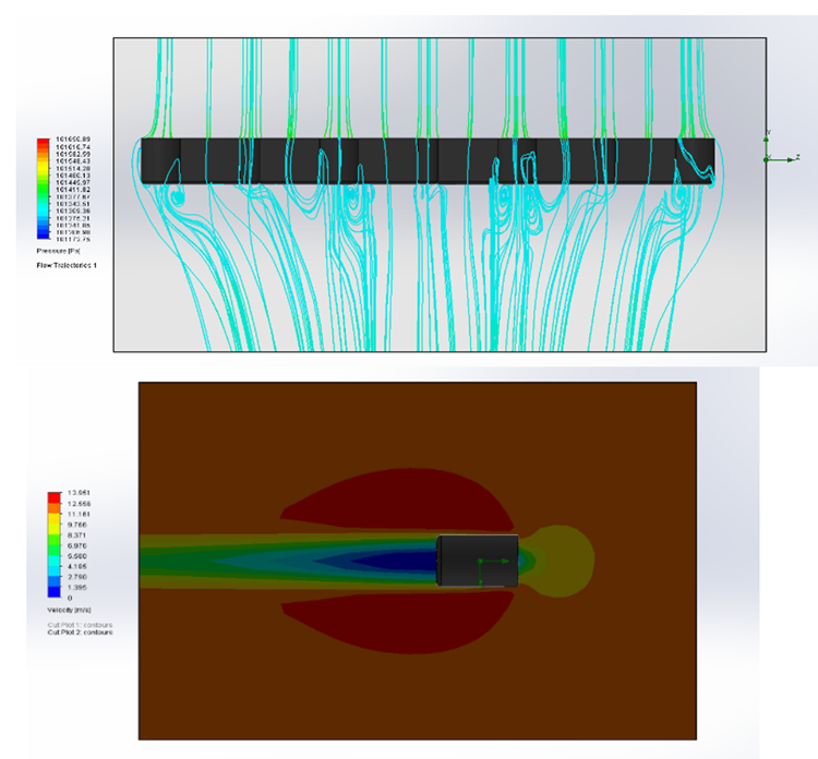
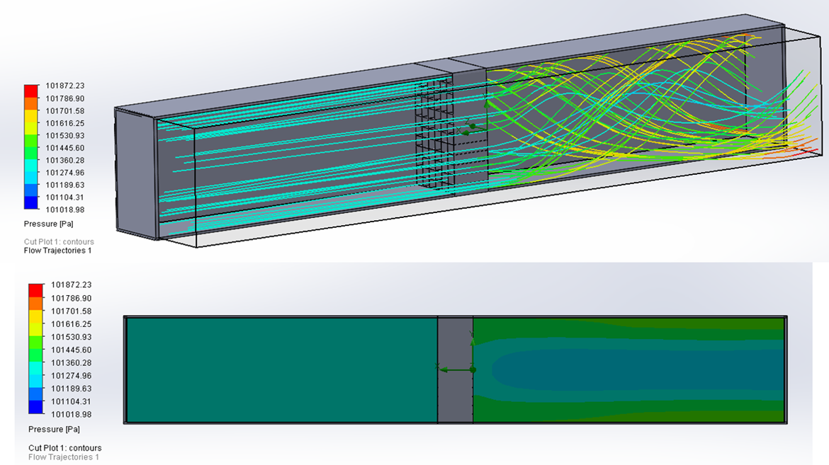
A CFD analysis was run on the aero rake members to verify that it would work as predicted before manufacturing.
The CFD showed that the air remained straight through the aero rake input channels, as well as over the webbed sections in between the cylinders.
There were vortices formed behind the aero rake because of the air going through the channels mixing with the air going around the outside at a different velocity as expected.
This would not be critical in the real-life scenario as the internal air would be travelling into a tube and won't mix with the outside air. What happens beyond this 'frontal plane' is not of any concern to the readings within the pressure tubes in any case, so would only impact the flow beyond the point where the readings were being taken.
Another advantage of the design is that it also produced a relatively small aerodynamic 'footprint'.
This is due to the thin, reinforced webbed sections that allows the designer to cut down on cross sectional thickness without losing rigidity.
Manufacture
The next step was manufacture of the aero-rake components, and to do this we would be taking advantage of the quick prototyping enabled by Additive Manufacturing. This would be achieved in-house via our Markforged Mark 2 3D printer.
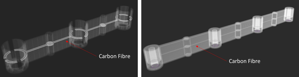
After the first prototype was printed without carbon fibre reinforcement, it was decided that reinforcement would be needed to reduce the flexibility of the components so that any vibration or flexure could be constrained when in use on vehicles or high-speed wind flow.
As a ressult, we decided to embed continuous carbon fibre reinforcement into the centre of both parts during the print as depicted below, and this achieved impressive results as expected.
After printing the parts, all support material was removed, and the parts were wiped clean with acetone. The acetone slightly smooths the nylon, creating a smoother surface and reducing the layer lines found on the outside of most 3D printed parts.
Small Scale Wind Tunnel Testing
The aero rake was then tested in terms of its durability and rigidity in a wind tunnel. The strength of the GoPro suction mount was also tested in the wind tunnel by running it for an extended period.
It was found that the aero rake was sufficiently rigid, and the minimal vibrations experienced did not affect the results as the manometer reading was able to stabilize during each test run.
However, it was picked up at this stage that the small-scale wind tunnel apparatus was creating fairly turbulent flow within the measurement region, so a plan was then devised to straighten the flow and produce something a little more laminar.
Flow Straighteners
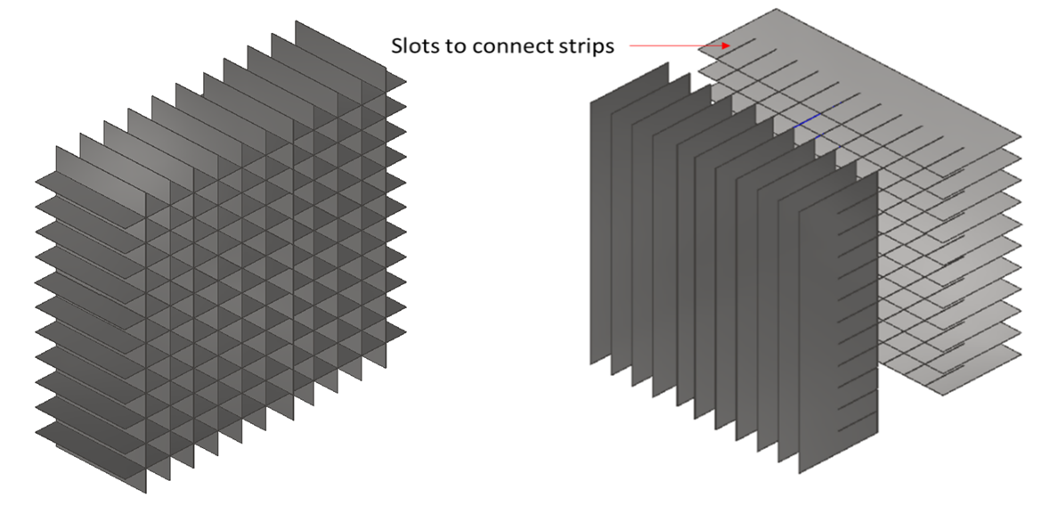
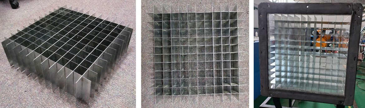
It was decided to focus on the inlet of the small scale wind tunnel appartus to see how the flow could be regulated at this point and, as such, an air flow straightener was designed and manufactured.
This would fit into the wind tunnel and straighten the incoming air flow. The apparatus had to be designed as to not restrict the flow rate of the oncoming airstream. Taking this into consideration the galvanised steel flow straightener concept was chosen as it was easy to manufacture and based on the CFD analysis, did not restrict air flow to a large degree.
A CFD analysis was conducted on the flow straightener before manufacturing to ensure that it would perform as predicted.
The CFD analysis showed that the flow straightener was very effective at straightening the turbulent air
The flow straightener was manufactured out of 0.8 mm galvanised steel sheet. A standard 2450 mm x 1225 mm sheet was cut into 22, 480 mm x 150 mm strips.
This material was chosen as the 0.8 mm thin section thickness would not restrict or disrupt the airflow through the tunnel and the galvanised sheet did not require painting or rust protection after manufacturing as it is already corrosion resistant..
After the strips were cut they were deburred with a deburring tool to prevent snagging or cutting on the sharp edges. The layout was optimized to reduce waste and use the smallest standard sheet available.
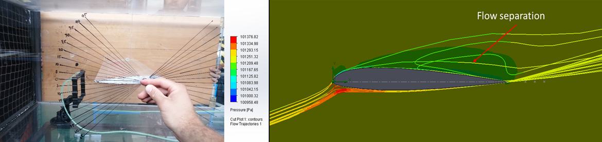
To test the efficiency of the flow straightener, string tufts were suspended from the entrance of the wind tunnel with, and without the flow straightener. The tuft test shows the laminarity of the air.
The tuft test is a simple and time-proven experiment - if the tufts are straight and have minimal movement when the wind tunnel is active, the flow is laminar; if the tufts are moving there is turbulence in the tunnel.
It was found that the flow straightener greatly reduced the turbulence in the wind tunnel, but the air was not fully laminar due to the short settling section behind the fan.
The turbulence caused by the fan reached the testing section. To fix this issue the wind tunnel would have to be extended significantly - this would form the basis of yet another future project, where the intention is to scale up the wind tunnel considerabl. For basic testing purposes in this case, the flow was sufficiently laminar to not be terminal.
A pressure drop test was also done on the flow straightener where the pressures were measured in front and behind the flow straightener (inside the wind tunnel) at three different positions to establish the loss in pressure and therefore velocity caused by the grid.
This velocity losses were confirmed with the air foil and airspeed sensor testing, as the rated airspeed of the wind tunnel was 18 m/s, but according to the measured pressures the air speeds were between 8 m/s to 11 m/s. All wind tunnel experiments discussed in this document used the flow straightener described above.
Air Foil Testing
After the flow straightener was installed and tested, testing of a NACA23012 air foil could commence. This would allow the verifaction of ojutput data as the air foil shape had well known outputs which the results could be compared to.
Before any testing could be done using the eDAQ Lite data capturer, the output had to be calibrated to a known pressure value, as the eDAQ provides a voltage output by default.
The pressures for the fan off condition and fan on condition were measured using the digital manometer. The eDAQ was connected to the same rake input as the manometer so that the voltage readings on the eDAQ could be calibrated to the pressure readings on the manometer.
The manometer measured 20 [Pa] when the fan was stationary and 82 [Pa] when the fan was on, and the reading had settled.
The eDAQ Lite measured 291.39 [mv] when the fan was off and 385.28 [mv] when the fan was running, and the manometer reading had settled.
These points were then used to plot the transfer function. The values were entered into the TCE software so that the voltage outputs could be automatically converted to pressures by the eDAQ.
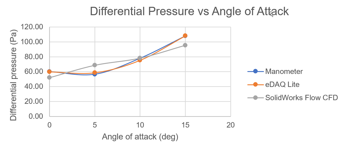
The CFD results varied from the eDAQ Lite and manometer readings by an average error of 10.79 % for the eDAQ and 10.72 % for the manometer, giving a final 10.76 % error between simulation and physical experiment. This is above the desired 5% error margin but is not unrealistically high considering all the delimitations for this experiment.
The error can be contributed to the effect of the fan creating a much slower air speed in the centre of the wind tunnel, whereas the CFD has constant airflow over the entire profile of the air foil. This caused the average pressures of the CFD to be lower than that of the physical experiment. This can be improved by including a fan in the CFD simulations to attempt to model the effects it would have in a real-life scenario.
This could also be improved by extending the physical wind tunnel test section so that the fan does not have such a major influence on the air flow on the components being tested. The extended test section length would allow the air to “settle” and help get rid of the turbulence caused by the fan blades rotating.
In addition to the eDAQ testing, pressure testing was done using a much more affordable ASPD 4525 Airspeed sensor and Arduino setup. This was done to prove that you do not always need the most expensive, high-end equipment to deliver good results.
The setup was done as follows:
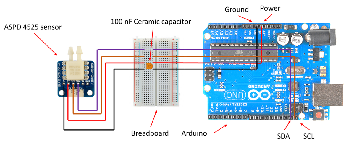
The sensor was then connected to the same tubing used with the eDAQ testing and the testing was done in the same manner as well.
Like the eDAQ, a transfer function had to be set up, but this time to convert HEX counts into pressure readings. It is evident that the transfer function produced an accurate prediction of the pressures read by the airspeed sensor.
The function produced an average error of 5 % over the three measured points. From the data it seems that the sensor favours better accuracy at higher speeds than lower speeds
This project served as an interesting to CFD and aerodynamic testing, and will be used as a foundation for a very exciting upcoming project involving the aero profiling of the Lamborghini Huracan GT3 EVO….
Events
The Aero Rake Project was on display at the 2021 RAPDASA Conference at the CSIR ICC in Pretoria.
The AEDG team was hosted at the EOS/Rapid3D stand throughout the event - much appreciation to all at Rapid3D...
Part of the Event included a visit to the impressive CSIR Wind Tunnel Facilities, where the team were shown through the facility and the various wind tunnels available there.This was particularly informative iro the future plans of the project, and also established a valuable connection for future collaboration. Much thanks are due to all at the CSIR Wind Tunnel facility for their time and willingness to share their experience.
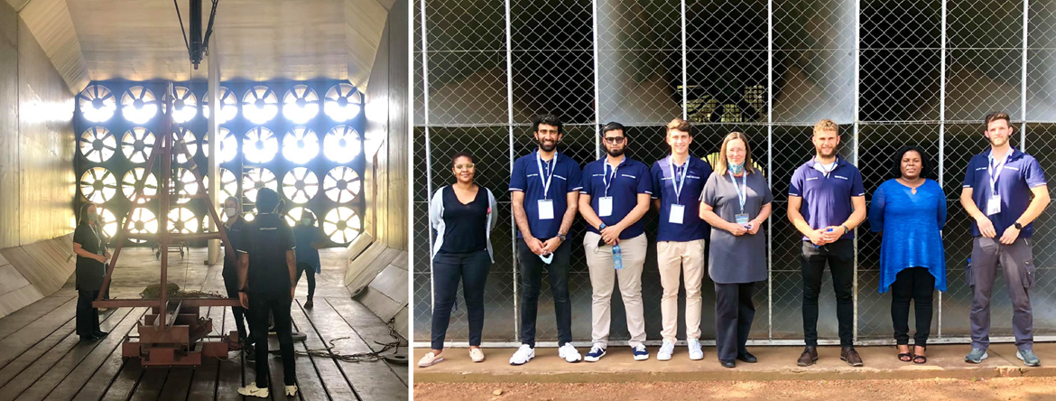
photos from visit to the Wind Tunnel facilities the 2021 RAPDASA Conference at the CSIR ICC
Contributors
Huge thanks & appreciation must go out to all these individuals for their completely selfless contribution to this, be it for information, advice, their time, their contacts, their services, or whatever contribution they made, no matter how big or small.
Custom Works (Arno Seyfert)
Scuderia Scribante (Byron Teengs: Team manager)
Rapid3D (Dave & Pauline Bullock)
NMU Mech Eng (Dr William Rall: Pressure Testing, Gideon Gouws: Wind Tunnel Model, Prof Hannalie Lombard: Data Analysis)
AEDG Team (Clive Hands, Jode Fourie, Muhammed Lookmanjee, Wian van Aswegen, Zaahid Imran)
eNtSA (Julien de Klerk: eDAQ setup)
NMU RE Lab (Damian Mooney: air pressure sensor)
Software Utilized:
SolidWorks Flow (CFD)
Inventor (Design)
SimSolid (FEA)
SOMAT TCE (data acquisition)
SOMAT Infield (data processing)
Arduino IDE (Arduinio programming)
Eiger (AM Slicing Software)