This project was carried out with the invaluable collaboration of
please see a full listing of all contributors at the bottom of this post
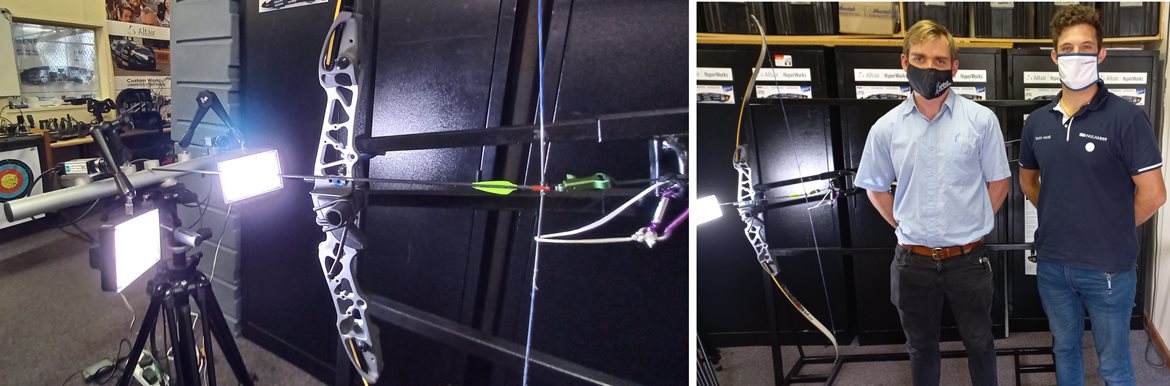
the final Recurve Bow with AM Riser and Handle
Project Outline
One of the AEDG students, Daniel Trask, is a keen user of compund bows as his hobby, and this project was initiated in tandem with his Honours level Research & Devevelopment module..
The task would be to focus on the design and manufacture, using Additive Manufacturing techniques, of the bow's riser and handle, which could then be applied to the associated components of either a compound or recurve bow, as used in both sporting and hunting applications.
Daniel has his own Compound Bows and has several years of experience of using and maintaining the devices, which put him in a good position to tackle this project.
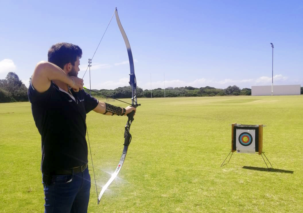
Daniel pictured above testing the Recurve Bow with test riser and handle on the back fields of the NMU - no students were killed in this experiment!
Overview
This projected was sparked from an interest and use of bows for hunting and target shooting. This project was completed as an Honours year R&D Project, with the hope of producing a physical prototype output of a Recurve Bow Riser and a bespoke handle customized to ergonomically fit the user's hand.
The project aimed to develop an understanding of the forces, stresses and strains, mechanics and energies involved with drawing and firing a Recurve Bow, to assist with design optimisation of the recurve bow.
Bow Risers have typically been manufactured using metals, like aluminium, owing to its great strength to weight ratio. In more recent times composites, like carbon fibre, are also being used. One major aspect to consider when choosing a material is achieving a balance between functionality and performance, ensuring that the material can perform and meet the preferences of various archers.
Additive Manufacturing (AM) is a fast-growing field, that allows for more intricate designs to be manufactured like never before. This project made use of Additive Manufacturing to design and print a prototype model of a Recurve Bow Riser. The processes and project timeline are discussed below.
typical aluminium bow risers
Initial Pre-Testing
Before the testing could commence, a shooting rig had to be designed and manufactured to assist with drawing and firing the recurve bow during testing. The aim of manufacturing this machine was to ensure repeatability and accuracy during the testing phase in order to benchmark an existing design.
Before any design work could be done testing on an existing riser was required. Mr Graeme Linder from Gray Archery supplied one of his Recurves Bows to be used for the various tests run. More information on the bow riser can be found on their website.
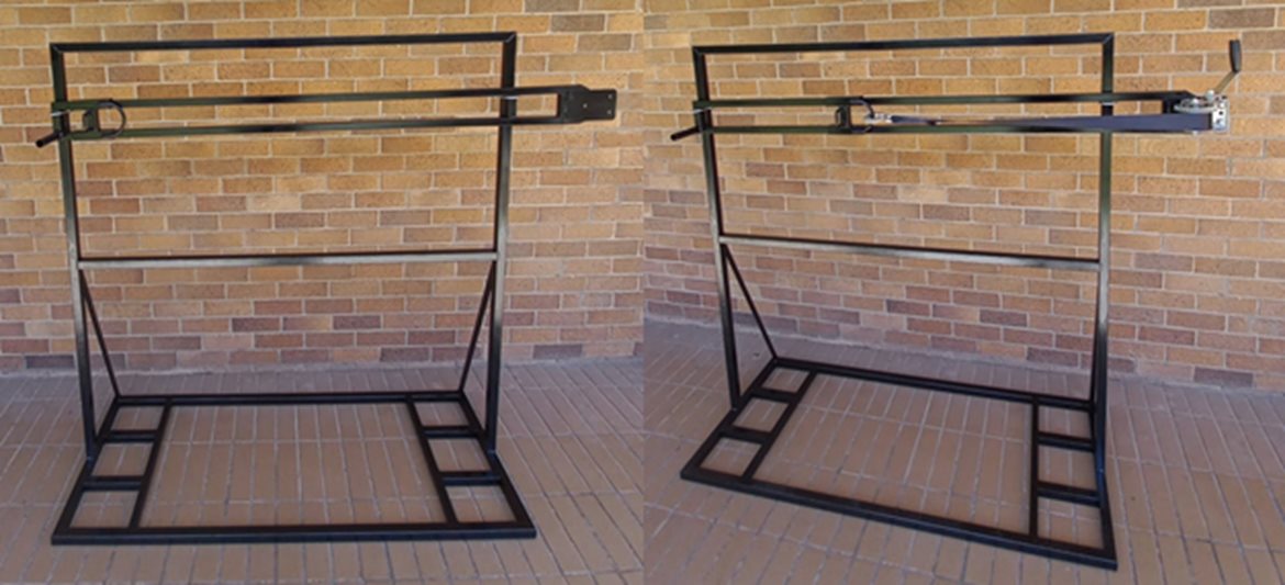
the fabricated test rig ready to be loaded with the bow
Components of Compound and Recurve Bows
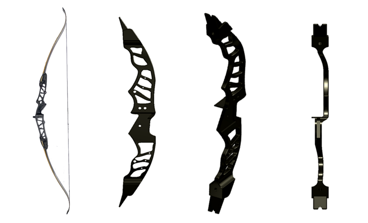
The diagrams below illustrate the difference and complexity of both a Compound and a Recurve Bow - because of the availability of a spare Recurve Bow, it was decided on focusing on the Riser for this particular Bow...
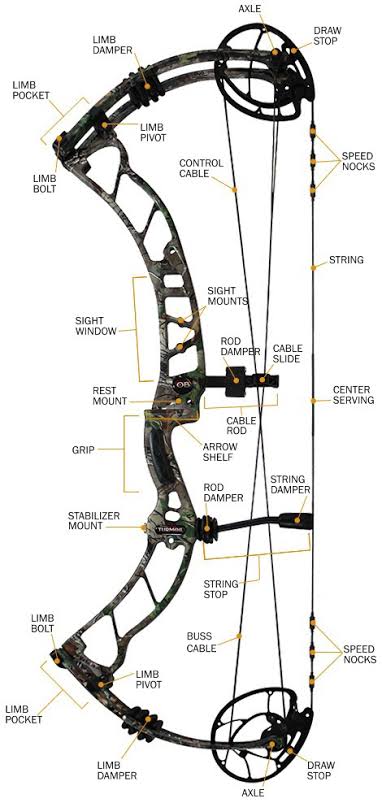
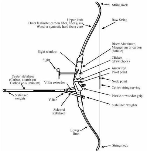
components of (left) a Compound Bow, and (right) a Recurve Bow
DIC Testing
The Digital Image Correlation (DIC) Testing apparatus was used to measure the stresses and strains being experienced by the bow riser while the bow was being drawn.
This data was used to understand the internal forces being experienced by the bow riser.
The DIC testing was completed and carried out in collaboration with eNtSA, a unit within the NMU focused on innovation and research in engineering. The testing was carried out under the guidance of Hubertus van der Merwe from eNtSA.
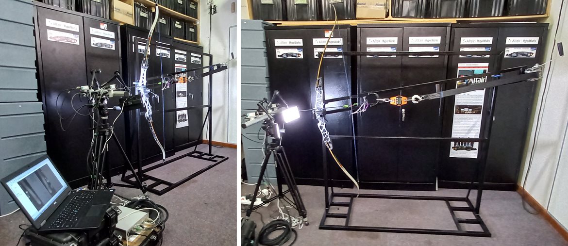
(above) the Test Rig loaded with the Recurve Bow and calibrated with the DIC apparatus
(below) Daniel and Hubert during the DIC set-up
Strain Gauge Testing
The strain gauge testing was used to measure the internal forces being experienced while the recurve bow was being drawn in the test rig.
The strain gauge data was used to compare to the results obtained by the DIC testing and validate these results obtained.
The strain gauging was completed under the guidance Dr. William Rall, who has significant experience in this field within the NMU.
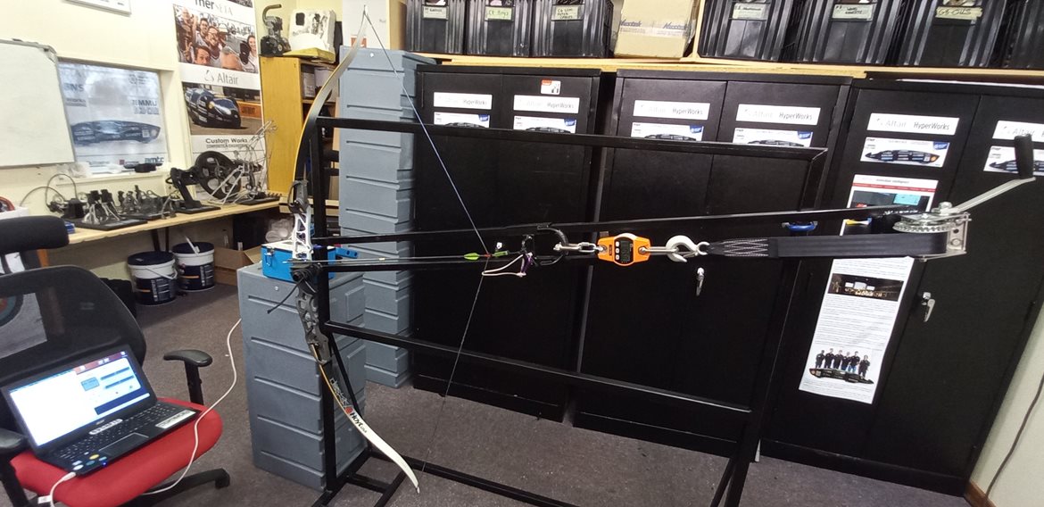
the bow with stain gauges attached and data being extracted on full extension
High-Speed Camera Testing
The high-speed camera testing was completed in collaboration with the Human Movement Science Department (HMS) at Nelson Mandela University.
This cross-disciplinary collaboration allowed for access to new technologies, equipment, and expertise.
The testing was carried out to develop and understanding behind the mechanics of the recurve bow and how energies are transferred during the firing of the recurve bow.
This testing was completed under the guidance of Ms. Courtney Musson, resident research expert at HMS.
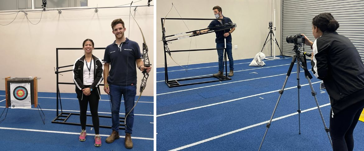
Courtney Musson (HMS Research Specialist) together with Daniel using the High-Speed Camera on a test firing
Quantification
One of the outcomes for the project was to identify if it was possible to quantify whether the hand of the riser would affect stability and have an impact on overall performance of the bow.
The results showed that there was an improvement in stability of the riser when a better accommodating handle for a specific archer was used compared to a universal handle.
This handle was designed, and 3D printed using ONYX on the in-house Mark Forged printers (discussed later).
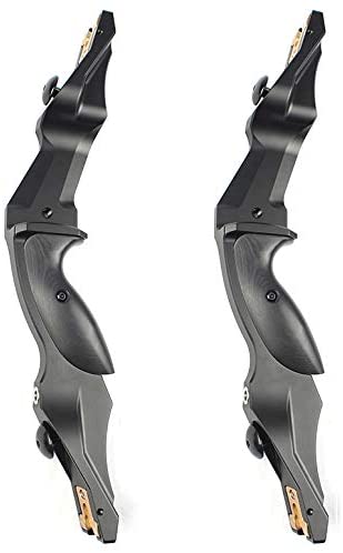
The handle was shaped according to a more comfortable fit based on a specific hand structure, instead of a “one-size-fits-all” design. The design of the handle can be viewed below.
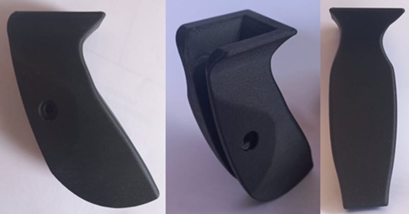
The redesigned prototype handles printed on the MarkForged AM printers
The data obtained from the DIC, and strain gauging was then used to set up and FEA model of the riser in question.
The FEA results were compared to the physical experimental results and validated.
The FEA was set up with the boundary conditions and forces calculated from the DIC and strain gauge testing results and were placed in a specific position that best represented a real world scenario of drawing the bow.
Boundary Conditions for one of the Simulations
Design
Once the testing had been completed there was a better understanding of the mechanics of the bow, the internal and external forces involved with drawing and firing a recurve bow.
The data and knowledge acquired during the testing processes, formed the basic knowledge needed to assist with the design of components, specifically the handle which was discussed above and the riser of the recurve bow.
The initial prototype design of the riser took a simple approach, and the design made use of smooth lines and shapes.
Initial Design Prototypes
The first prototype was printed in several parts owing to the print bed size of the Markforged printer and glued together.
The completed and assembled riser can be viewed below.
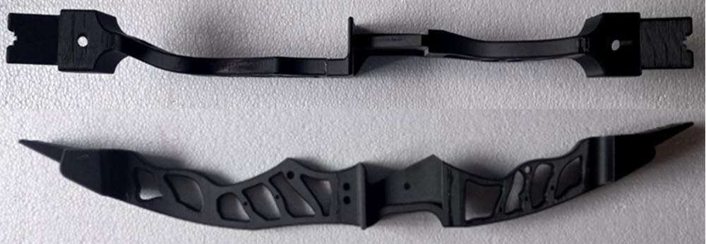
Initial Printed Design Prototypes in ONYX
The second protype looked at using the base form of the initial prototype and use topology optimisation to generate a unique design, in terms of overall design.
This design was completed within the Altair Inspire software package.
With a bow, in most cases a heavier bow is preferred as it assists with stability and thus the topology optimisation was used to reduce some mass but not too much to ensure stability could possibly maintained, this design was a prototype and would have needed to be tested to confirm these assumptions made.
Due to time constraints the 2nd prototype could not be printed.
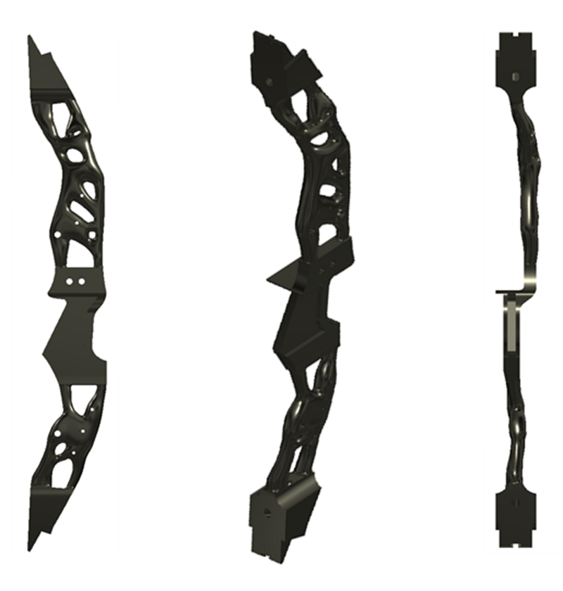
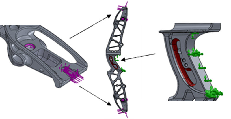
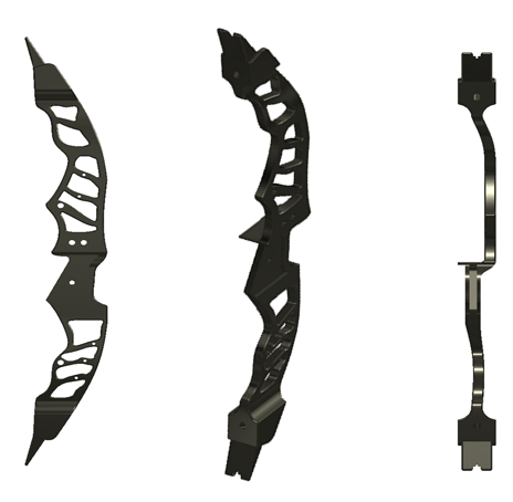
Topology Optimized Design Prototypes
A third prototype was also created using the same base design of the first prototype and followed the steps shown below to generate the initial design of prototype three.
This prototype lattice design was completed within the nTopology software package. Due to time constraints the design remained in its raw state, with plans of completing the design soon.
The images below show the initial base design of the riser in nTopology, the model was split, and the two large sections were meshed to allow for these solids to be processed and generate the lattice displayed in the final image.
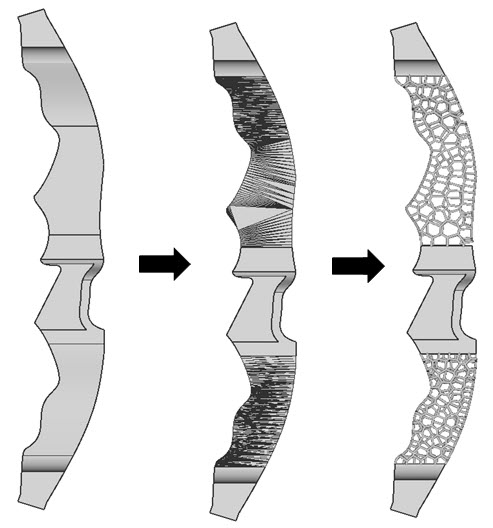
Third Latticed Design Prototypes
Events
The Recurve Bow Riser together with a comparative Compound Bow was presented at the 2021 RAPDASA Conference at the CSIR ICC in Pretoria. The AEDG team was hosted at the EOS/Rapid3D stand throughout the event - much appreciation to all at Rapid3D...
This somewhat left-field application of Additive Manufacturing techology and DfAM techniques elicited much interest amongst the attending delegates, even though they were strictly banned from a test fire themselves!
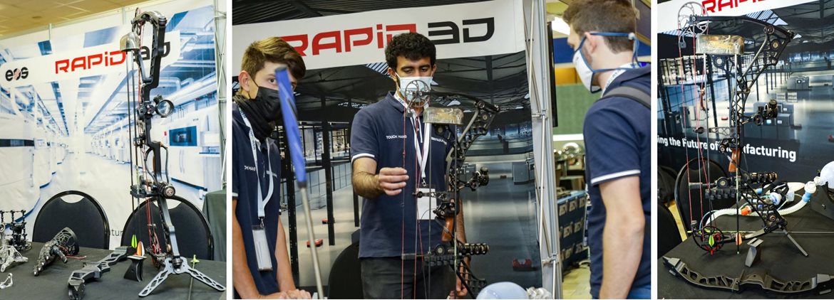
various photos from the 2021 RAPDASA Conference at the CSIR ICC where the Riser designs generated much interest
Contributors
Huge thanks & appreciation must go out to all these individuals for their completely selfless contribution to this, be it for information, advice, their time, their contacts, their services, or whatever contribution they made, no matter how big or small.
Gray Archery (Graeme Lindner)
eNtSA (Hubert van der Merwe - DIC analysis)
NMU Mech Eng (Dr William Rall: Strain Gauging, Amish Lalla: Design, Sherwin Casling: Welding)
NMU Human Movement Sciences (Courtney Musson)
AEDG Team (Clive Hands, Jode Fourie, Muhammed Lookmanjee, Wian van Aswegen, Zaahid Imran)
Software Utilized:
SolidWorks (FEA)
SimSolid (FEA)
nTopology (lattice generation)
Altair Inspire (topology optimisation)
Altair Inspire Motion (dynamic simlation)
Autodesk Inventor (CAD design)