This project was carried out with the invaluable support of the Faculty
Teaching Development and Innovation Fund (TDIF)
please see a full listing of all contributors at the bottom of this post
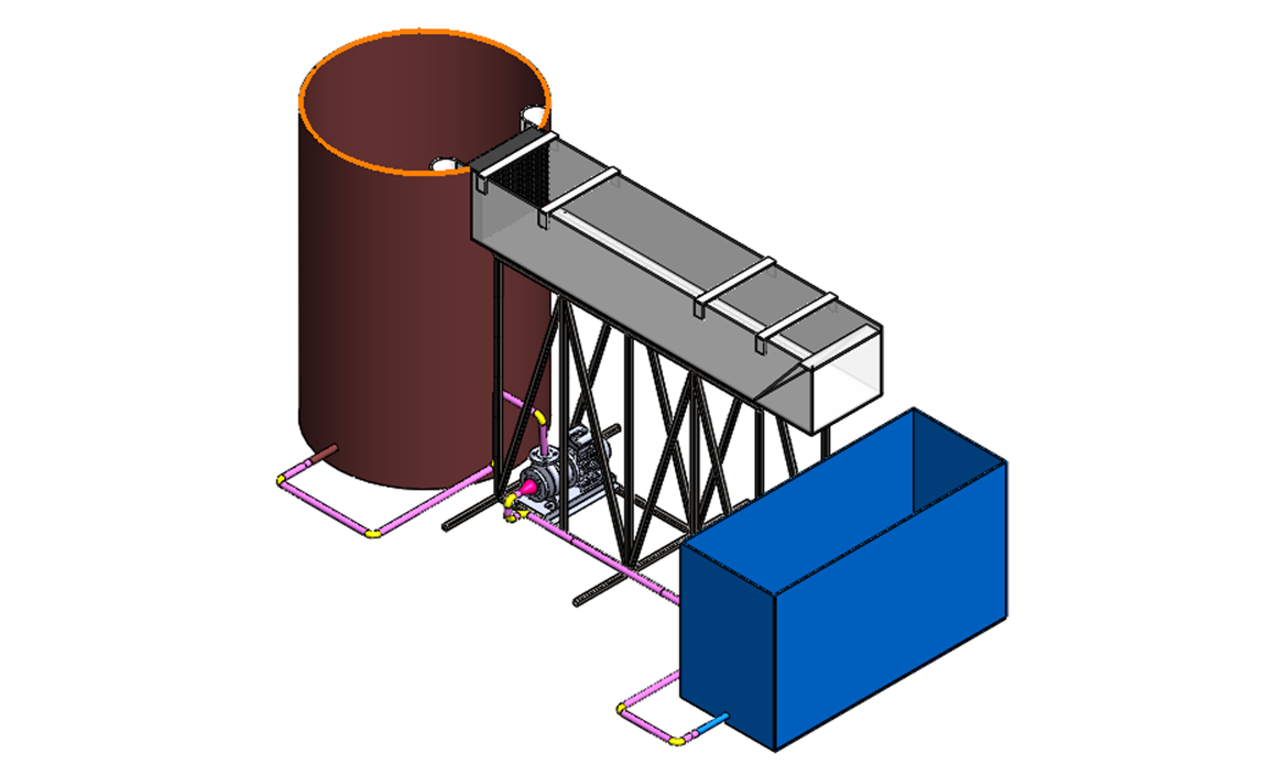
a schematic of the intended Water Channel experimental device
Project Outline
The move into fluid flow analysis and CFD with other research projects necessitated the need for an experimental test bed to verify computational simulations.
As a wind tunnel is just logistically and financially impossible, the idea formed to design and build a water channel for flow visualization that could then also serve as in-house experimental equipment for future NMU Engineering students.
This would provide the opportunity for future aerodynamic projects for Nelson Mandela University.
the NASA Ames water channel which was the basis for the design of the NMU water channel
The Reynolds number scaling between water and air allows for results from simulations in air to be reasonably compared to real-world results within the fluid channel due to a Reynolds number difference of the 3rd order, which is far more easily achievable than with a wind tunnel.
As such, the objective of the project was to design & manufacture a water channel apparatus, using simulation to ensure that laminar flow would be present within the channel section.
The design was based on an existing water channel built by the NASA Ames Research Center and used successfully on many fluid flow verifications.
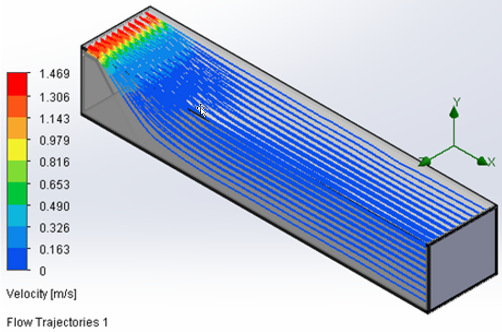
simulation flow trajectories confirming laminarity int he overall channel
To prepare the design, many simulations and iterations were done on the water channel components to determine the optimal tank size, flow straighteners and testing positions within the channel itself.
This was further supported by structural analysis on the structural components to ensure that the support structure was also strong enough to support the full working assembly.
To assist the design, a basic flow simulation was done on just the channel section to ensure that the anticipated inputs were correct, and this produced laminar flow trajectories within the channel.
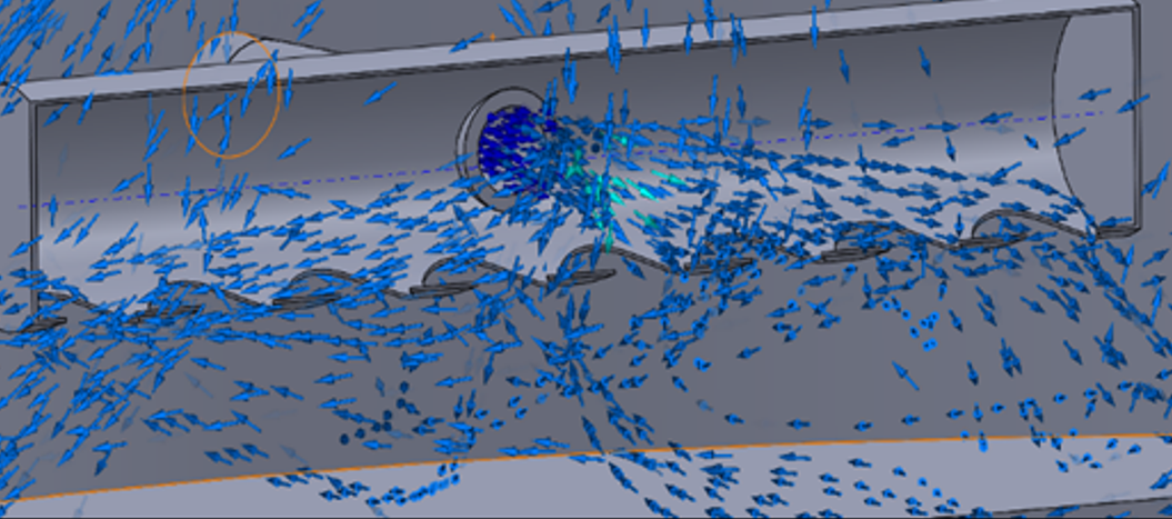
simulation flow trajectories showimg inlet turbulence
Care was also taken to reduce the turbulence in the upstream supply tank to ensure the upstream water is allowed sufficient settlement time from turbulent to laminar as the water rises to the top of the tank, providing an improved value on the NASA tank from 25.5% to 15.8% for the NMU tank. These values were both probed at the inlet to the channel.
A PVC pipe diffuser was also introduced to reduce the turbulence at the inlet of the channel which also reduces the amount of sloshing in the tank, and simulations carried out to verify the further reduction of turbulence in this sector of the structure.
Further simulations were carried out to determine the optimal geometry (square or honeycomb), cell size and thickness of a modular flow straightener. This was achieved via a parametric study varying the thickness parameter, and the simulations resulted in a turbulent intensity of 0.5% which is classified as laminar flow.
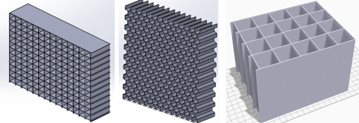
(from left): both Square (left) and honeycomb (right) configuration flow straighteners were considered before settling for a sectional square design
The final flow straighteners were printed in sections in Onyx material on the in-house MarkForged 3D printers. The overall flow straightener was divided into 6 sections to ensure the parts fitted onto the bed of the 3D printer, and then would be assembled together after the fact by glueing them together.
The next area was to determine the optimal testing position for the test specimen within the water channel itself. A parametric study was used to vary the fluid speed to locate the optimal testing view position.
The water channel itself would be constructed from Perspex sheet and glued using PVC cement and allen-head bolts will be used for extra strength. This was all achieved in-house using the assistance of the technical staff.

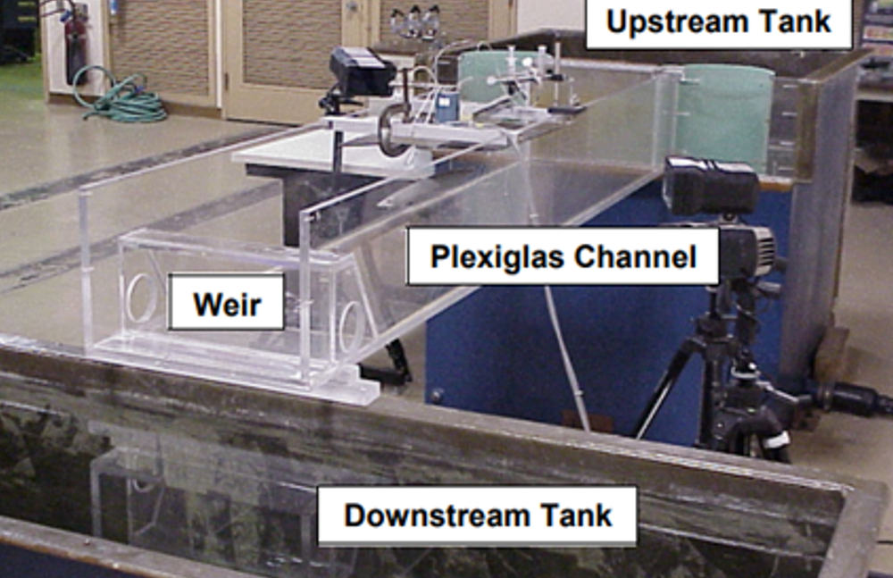
the main flow study section undergoing constructions in the Fluids Lab early in 2023
The channel support frame was designed as a basic space truss structure, using square tubing to maximize stiffness and load-carrying capacity. The lengths were cut and welded together in the Machine Shop to construct the frame to support the channel.
The design & development of the water channel was finished in late 2022 with the intention of construction & testing in the first half of 2023, which is currently taking place.
All major components & accessories were procured in late 2022 in preparation for the build phase within the budget provided by the TDIF funding.
The finalized apparatus will be housed in the Fluids Lab (E002) together with other fluids practicals, and will form not only an additional resource iro any CFD research done, but will also form the basis for verification practicals for future undergraduate students in the Fluids stream of study within engineering.
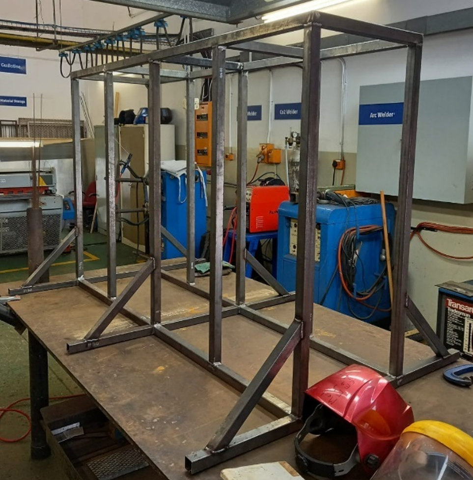
the water channel frame undergoing construction in the Welding Bay
Contributors
Huge thanks & appreciation must go out to all these individuals for their completely selfless contribution to this, be it for information, advice, their time, their contacts, their services, or whatever contribution they made, no matter how big or small.
Custom Works (Arno Seyfert)
NMU Mech Eng (Dr William Rall, Gideon Gouw, Sherwin Casling)
AEDG Team (Clive Hands, Brian Jack, Jode Fourie, Wian van Aswegen, Cameron Grunewald)